Controlling an RGB Light Strip over WiFi
I had one of those RGB light strips hanging around, so I decided to put it up above some windows. When I bought it, it came with one of the IR color-remotes, which is great, but it didn't have a ton of range, and certainly limited my capabilities. So, like my last project (smart outlets), I decided to learn how to hook up a Particle to it, so I can control it over wifi.
Warning
There are plenty of risks when working with electricity. I am not responsible for fires, explosions, or electrocutions you may encounter while creating your circuit. My post is my personal learnings, which may be flawed, missing information, or non-reproducible. Be careful, and do so at your own risk.
Parts List
- Particle Photon
- 3.3V Switching Converter
- Capacitors 10µf
- N-Channel MOSFET
- DC Barrel Jack
- 12V 3A Power supply (I had one on hand)
- 330 Ω Resistors
- Solderable Breadboard
- Connectors (I used JST)
- Heat Shrink
- Wire (At least 26 gauge).
- I used a voltmeter on my LED strip and saw max current of 1.8A. If you have more current, you might need thicker wire. See gauge reference
The Design
I sat down for quite some time designing a circuit for it. The big problem for me here was that the light strip took 12 Volts, but the particle is either 5v or 3.3v. A lot of googling, and folks were suggesting just having two different power supplies: The particle powered via USB, and a separate power supply for the lights. I viewed this as a challenge to only have 1 power supply.
I did some research, and first landed on a linear regulator, but that converts excess power into heat.. and it's a lot of heat to step down 12 to 3.3v! Not so hot that I couldn't touch it, but too hot that I didn't want to leave it plugged in.
I ended up buying a switching converter from digikey. It was perfect, and stays very cool throughout operation.
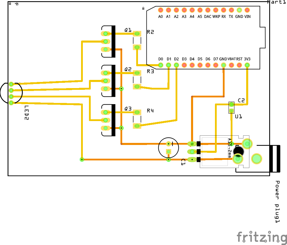
That's the rough idea. That diagram is currently using the linear regulator. If you decide to buy the switching converter, make sure to follow it's recommended setup for the capacitors. Also double-check the pins! Different converters can have slightly different pin setup.
Be careful which pins you hook up the Particle with. The 3v3 pin can accept input, but is strictly 3v3. You can also connect to the VIN pin, but that needs to be closer to 5V (see the datasheet for exact specs).
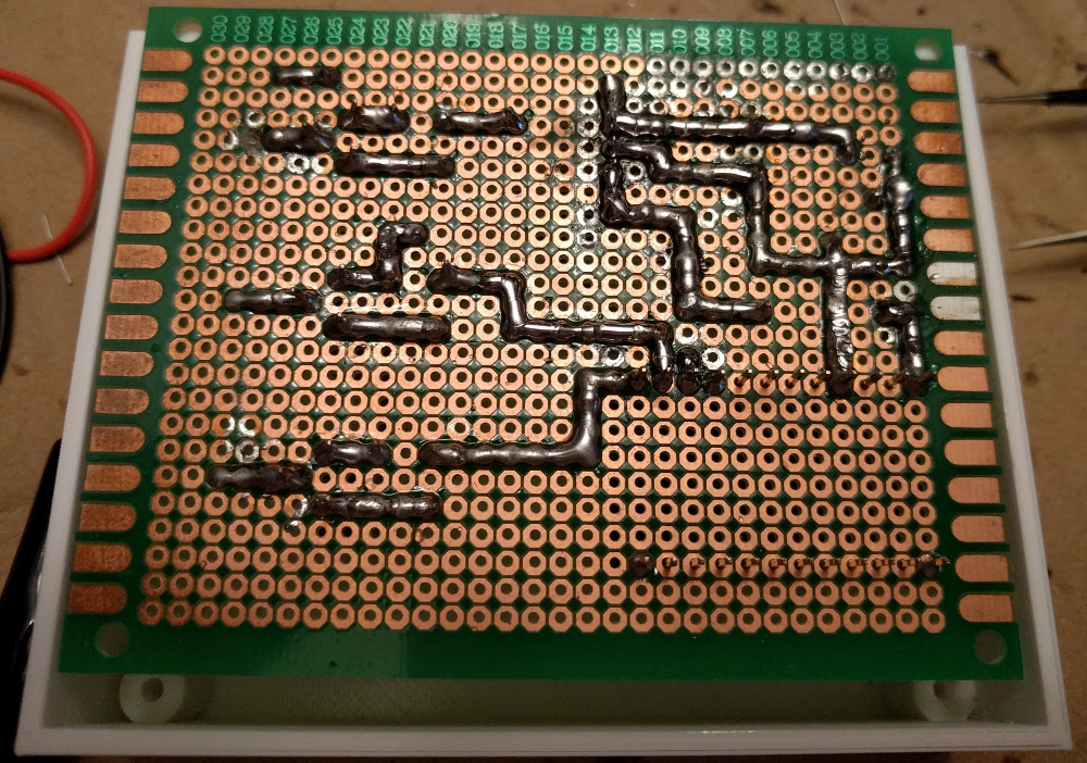
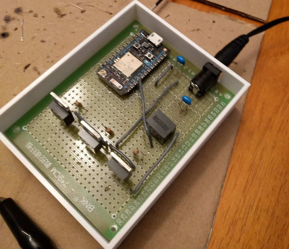
Putting it Together
I can't tell you how long this took to do, and how much solder I wasted.
I'd recommend running wire between the pins, rather than soldering.
But it looks kinda nice.
The Box
Luckily for me, at about this time, my brother was getting into his 3D printer and CAD design. He offered to make a small box for my electronics as long as I paid for materials. Custom made box for only $2? How could I say no!
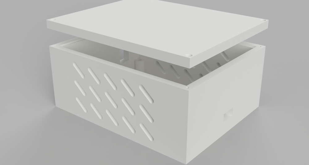
Important: The way the current box is configured, the DC port ended up being too small and I had to widen it after-the-fact. Your mileage may vary.
Uses M2 Self-Tapping screws, 7mm
The Software
Right now, the software on the device is very simple. Just a target color and a smooth-ramp.
I'd love to be able to have this react to music, or have color-gradient "programs". If I do that, I'll write another post about it in the future.
Outcome
I did a fair amount of wire soldering with some heatshrink and JST connectors to run the wires up to my case.
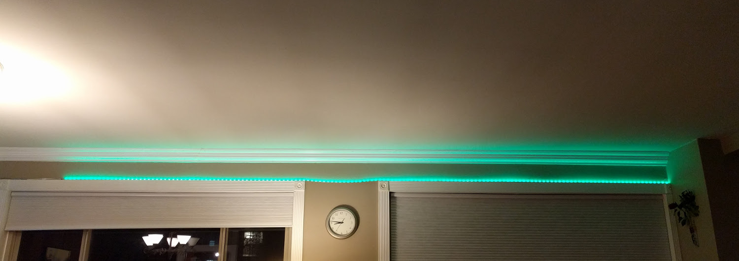
I am very happy with the outcome. I learned quite a bit about higher voltages, and heat loss.